Various PIC Projects
Here we list some fun projects one can do with 8-bit PIC microcontrollers.
For instructions on how to program the chip using the PicKit2 for the various projects, see
pprogs.html .
New Laser Gate
The new laser gate project is described at lasergate2.html.
The implimentation of our new version can be used in linux, or in windows where we read
the gate using Nodejs. For the Nodejs version, see
nodeprogs.html.
Kitchen Timer
The kitchen timer is a timer that allows one to set the time in minutes up to
63 minutes. When the time is up, a buzzer goes off. We use the PIC16f690
microcontroller. The remaining time is displayed in binary format using
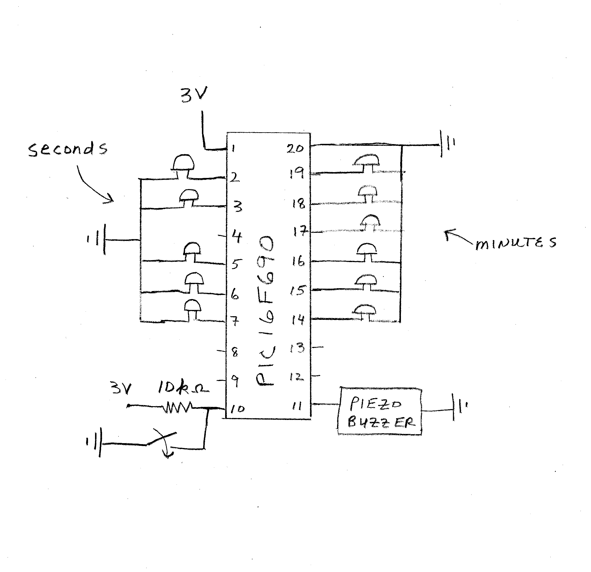
LED's. There are 6 LED's for the minutes (pins 14-19), and 5 LED's for the seconds
(pins 2,3,5,6,7). Pin 11 is connected to the buzzer. Pin 10 is connected to
a button that allows the user to add a minute to the timer.
One can construct the timer
by placing the components
onto a solderless breadboard,
or by soldering the components
onto a perf-board. The connections
are shown in the figure to the right:
|
|
For the seconds, the most-significant-bit is pin 7, and for the minutes the
most-significant-bit is pin 14. The second LED's count up to 30 then back
down to zero in binary. The timer starts out at one minute, and one can
push the button to add more minutes to the timer.
Click here to see a
parts list .
The assembly code for the timer is
kitimer2.asm .
The minutes are displayed in binary on pins 19 -> 14, with the lowest
significant bit being pin 19. The seconds are displayed on pins
7,6,5,3,2, with the lowest significant bit being 2. The 10k Ohm resistor
on pin 10 is used as a "pull-up" resistor for the button. When the button
is pressed, pin 10 is grounded yielding a "zero".
Square Wave Generator
The square wave generator produces a simple square wave, and for this project we use the
simplest PIC chip, the PIC12F629, with only 8 pins. The assembly code for the square wave
generator is sqwave.asm. The square wave output is on pin 5.
The output on pin 5 is: +3V for around 10 msec, 0V for around 10 msec, etc. You can change
the timing of the square wave by adjusting the parameters in the subroutine delay1.
After compiling the assembly code into hex using MPLAB, I load the program on the chip
using the pickit2 via the software "pik2cmd". One can do this in a linux terminal by typing
"pk2cmd -PPIC12F629 -M -F./*.hex".
Polar Chest Belt Reciever
I wanted to make a simple receiver for Polar's T31 chest belt transmitter, that would
indicate the detection of a heart beat. For this task, we use the 8 pin PIC12F629
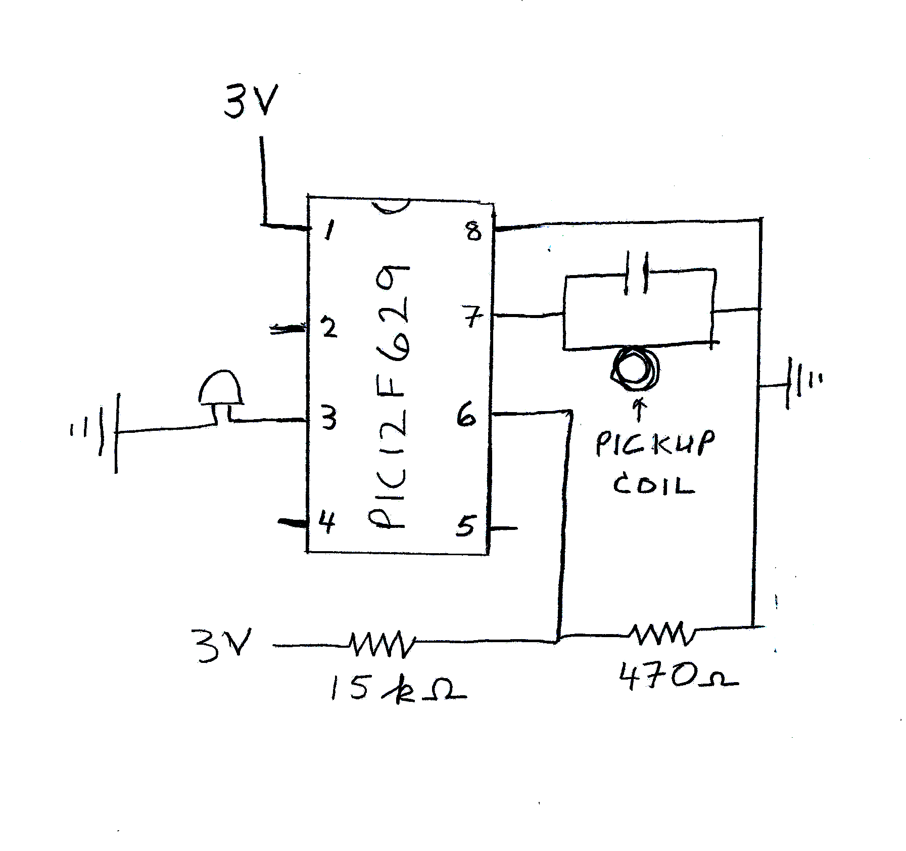
and make use of its voltage comparison feature. The assembly code is
hrbeat.asm, and the circuit is shown below.
|
The T31 belt transmits a 5 kHz signal that lasts for 7 msec every time a heart
beat (i.e. R peak) occurs. A coil is used to pickup the signal. The coil is connected in parallel
with a capacitor to pin 7 of the chip. The coil and capacitor are chosen to have a 5 kHz resonant frequency.
Two resistors are connected in series to pin 6 of the chip and act as a voltage divider to
provide a comparison voltage of around 0.1 volts on pin 6. When the voltage on pin 7 becomes
larger than that on pin 6, the 6th bit of CMCOM goes high. The led on pin 3 is then lit for around
10 msec.
|
As with the square wave generator,
the assembly code is compiled into hex using MPLAB. Then the program is loaded on the chip
using the pickit2 via the software "pik2cmd". One can do this in a linux terminal by typing
"pk2cmd -PPIC12F629 -M -F./*.hex".
RR-Interval Timer
With the RR-Interval timer one can record and save the time between heartbeats, the RR-interval,
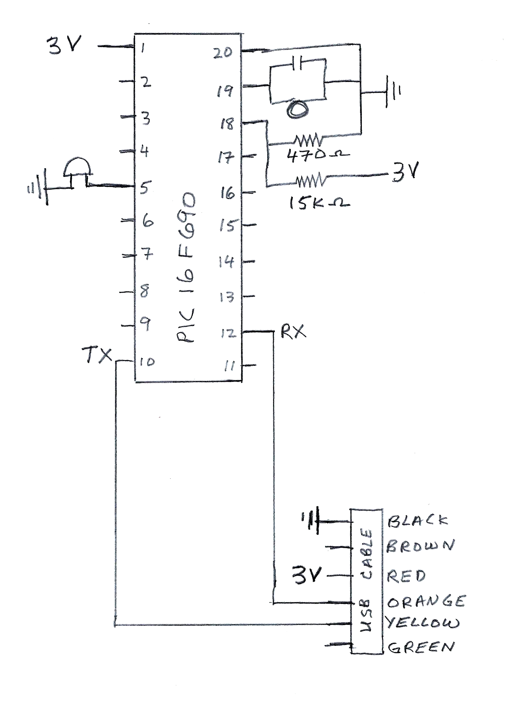
using the polar T31 chest belt. A PIC16F690 is programmed to detect the signal from the polar
belt as above. Then the chip records the time and sends the data via usb to a PC for analysis.
There are three computer programs used in the project: an assembly code for the PIC chip, a
nodejs program for record and save the data, and a html browser program to analyse the data.
The PIC assembly code is:
rrinterval.asm, and and circuit for the chip is
|
As before, a pickup coil is connected in parallel to a capacitor and connected to pin 19. The coil
and capacitor have a resonant frequency of 5 KHz.
Two resistors, 15K and 470 Ohms, are connected in series to pin 18 of the chip and act as a voltage divider to
provide a comparison voltage of around 0.1 volts on pin 18. When the voltage on pin 19 becomes
larger than that on pin 18, the C1OUT bit of CM1COM0 goes high. A time stamp is recorded using the
TMR0, T1, T2, and T3 bytes. The four time bytes are send via usb to the PC. Finally,
the led on pin 5 is then lit for around 10 msec.
|
As with the square wave generator,
the assembly code is compiled into hex using MPLAB. Then the program is loaded on the chip
using the pickit2 via the software "pik2cmd". One can do this in a linux terminal by typing
"pk2cmd -PPIC16F690 -M -F./*.hex".
The data is received and recorded using the nodejs program:
rrheart.js. To install and run nodejs programs, see
nodeprogs.html.
The program saves the RR-interval data in units of milli-seconds to the file dataout.txt.
The data can be analyzed using the app
rrbasic.html.
Sport Timer
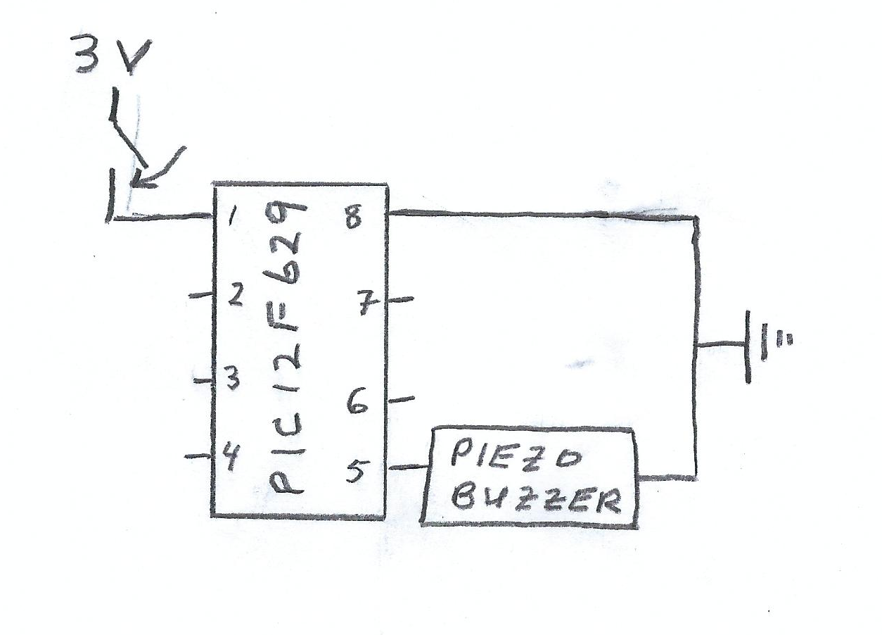
The sport timer produces "beeps" every minute that indicate how many minutes
have elapsed. For this project, we use the PIC12F629. The assembly code for the timer is
jogtime2.asm . Note: delay2 is the subroutine to
delay one minute. For our PIC12F629 chips, the crystal did not advanced the onboard clock
by exactly 2 microseconds, so we had to adjust our timing. Be sure to check the timing when
programing the PIC12F629.
One can construct the timer
by placing the components
onto a solderless breadboard,
or by soldering the components
onto a perf-board. The connections
are shown in the figure to the right:
|
|
Every minute the timer makes 6 "beep" tones with the piezo buzzer.
Each tone is either a low note = zero, or a high note = one. Thus,
the user will hear 6 consecutive bits. There is a short pause after
the first two bits. To convert the 6 bits to
the number of minutes, we used a modified binary scheme. The first
two bits determine the quarter of the hour. That is 00 is the first
quarter, 01 the second quarter (or 15 minutes), 10 the third quarter (or
30 minutes), and 11 is the fourth quarter (45 minutes). The next
4 bits determine the number of minutes past the quarter. For example,
01 1001 would translate to 15 + 9 = 24 minutes. The largest number
is 11 1110 and equal to 45 = 14 = 59 minutes. After the 59th minute,
the timer starts the cycle over again with 00 0000.
When the switch is closed to turn the timer on, the timer beeps 6 low
notes, 00 0000, corresponding to zero minutes.
Click here to see a
parts list .
Siegel's Home Page
Physics Department|
College of Science