Setting up the PIC Microcontroller
The following programs are examples that I use for teaching the programming
of 8-bit PIC microcontrollers. A good reference is the book "Designing Embedded
Systems with PIC microcontrollers: Principles and Applications"
by Tim Wilmshurst. The datasheet for the PIC is also a good reference
for information on the bits for each memory address register in the chip.
The method we use is to program the PIC chip using the PICKit2 in assembly
language. The PICKit2 is relatively inexpensive and services a large
variety of PIC microcontrollers. We usually start with the PIC16F690
microcontroller since it has just about everything we need and has
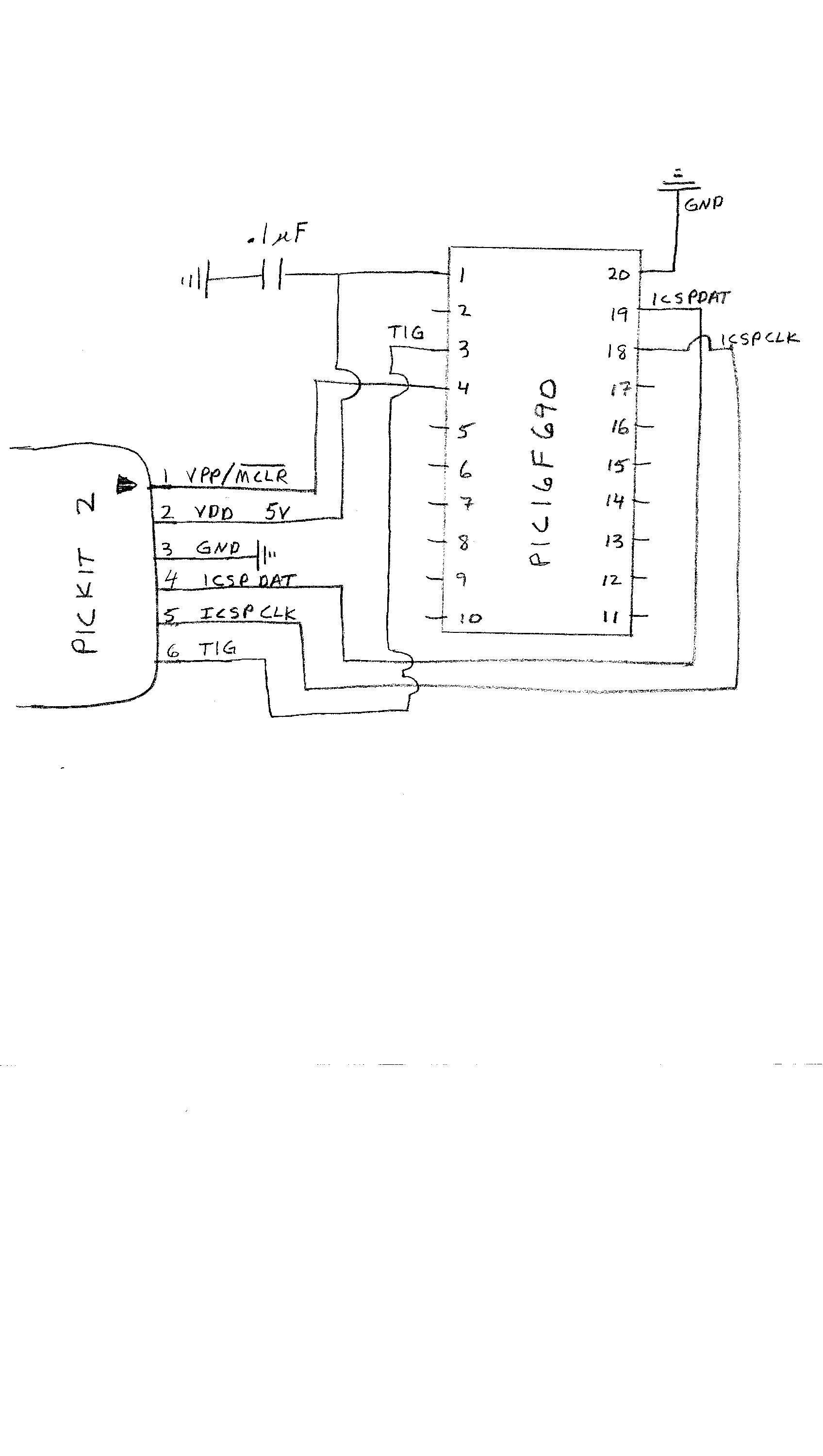
a small pin count (20). Placing the PIC16F690 in a breadboard, We use the PICKit2 "only"
and connect our own 6 wires from the PICKit2 to the microcontroller as shown in
the diagram
Pickit2 circuit.
We carry out the
following procedure to test our system. Programming is done using the MPLAB (free download)
software from microchip in assembly.
- First program the PIC chip with the program
test.asm,
which puts 5 volts then 0 volts on pin #16 (C0).
- Check the output of pin #16 with an oscilloscope. One should see a 5 volt output
that lasts 1 micro-sec (for a 4 MHz clock), and 0 volts that lasts for
3 micro-sec. If this works, then we know that we have set up the programmer and chip
correctly.
- Next we check the serial transfer, since we will want to receive and save data we
send from the microcontroller. As a first check we program the code
sertest1.asm,
which sends the same number via serial at 9600 BAUD
- To check if the serial output is working, we connect the oscilloscope
to the TX pin (#10 for PIC16F690). The output for a zero in the binary number should be 5 volts lasting
1 micro-sec (for 9600 BAUD). The output for a one in the binary number should be 0 volts lasting
for 1 micro-sec (for 9600 BAUD). There will also be a start and stop bit, so the complete
signal will be 10 bits long.
- If the TX pin is producing the correct output, there are two ways that we can
read the serial data with the PC: using a TTL-232R-5V cable to usb, or using
a MAX232 chip to a serial port. The former method is simple and easy to use.
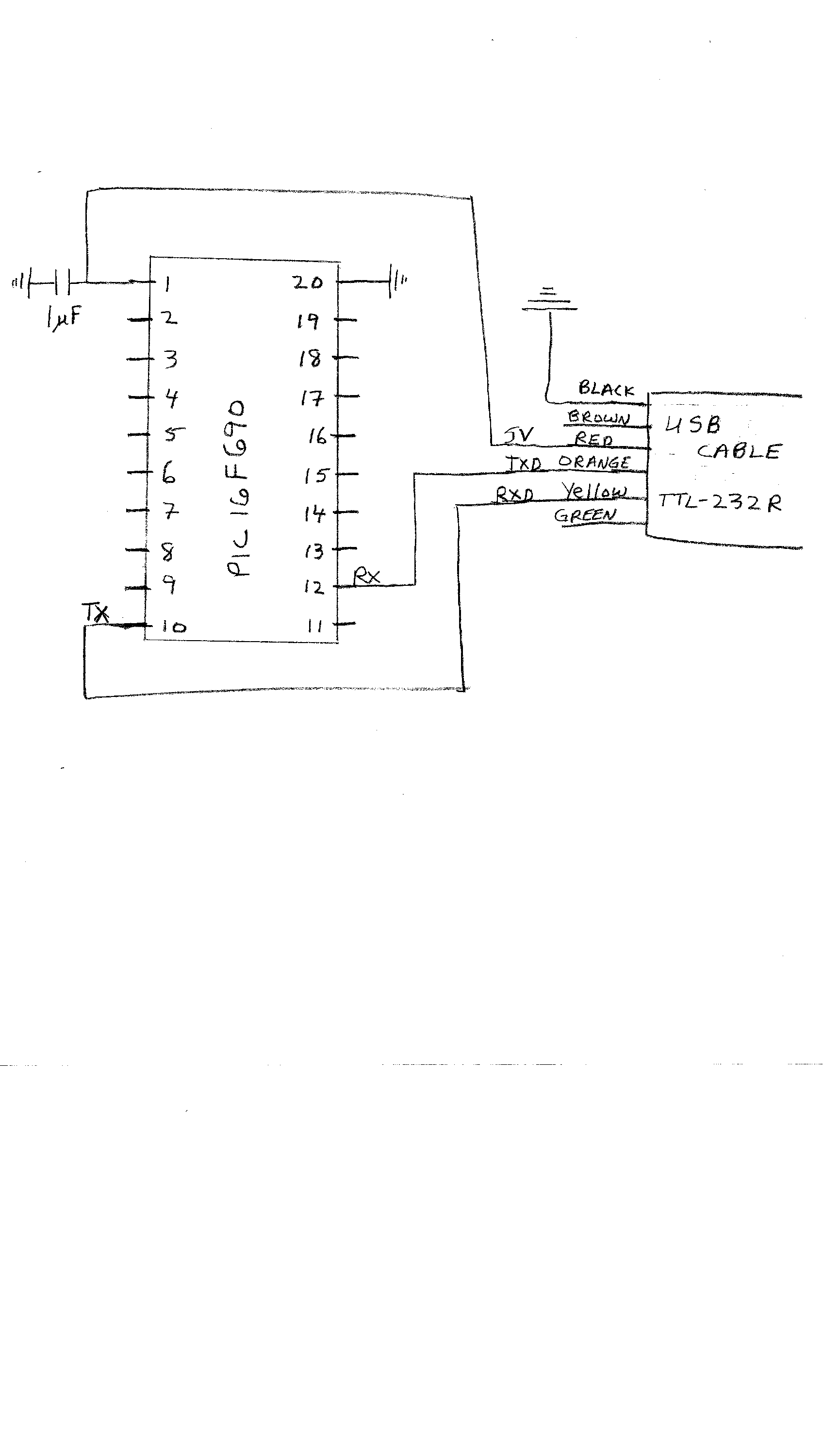
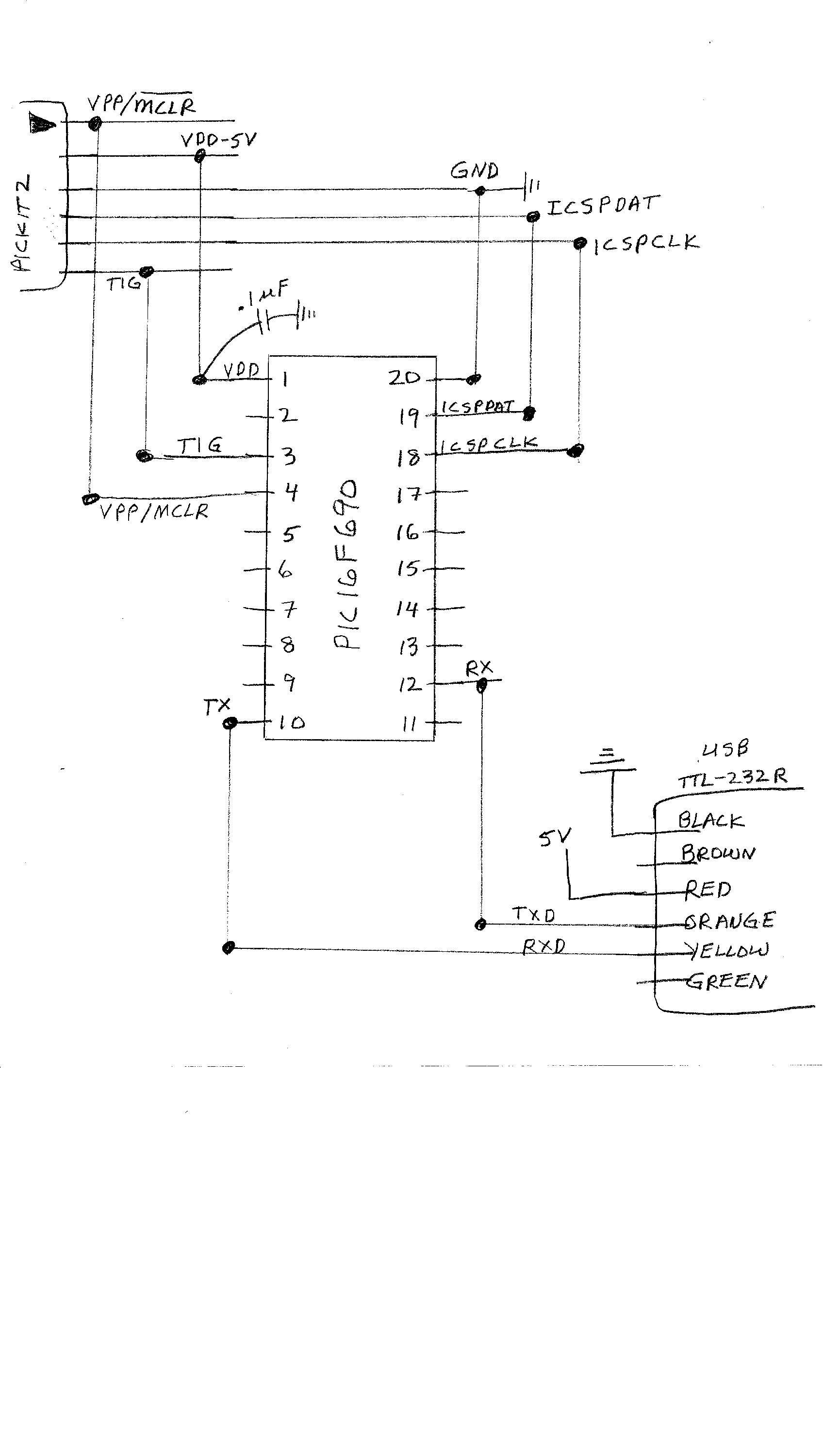
- USB input to PC: The easiest way to transfer data from the PIC to the PC is to use a
TTL to USB cable: TTL-232R-5V (straight connector) or TTL-232R-5V-WE (wire ends)
made by FTDI. The cable has 6 leads, 4 of which are connected directly to the
PIC pins. See
PIC-usb connections for a circuit diagram of the connections.
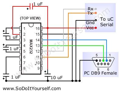
- SERIAL PORT input to PC: If one wants to input to a serial port, then the MAX232 chip provides the
appropriate voltage shifting for the port. The MAX232 chip will shift 5 volts to +8 volts and 0
volts to -8 volts for input to the serial port. See
max232 circuit (compliments of www.SoDoItYourself.com) for
the circuit diagram to connect the PIC to the serial port. To check the circuit,
we read the output of the MAX232 chip with the oscilloscope
to insure that the correct +/- 8 volts represents the binary number.
- Finally, the asynchronous serial output to the PC is read in the Linux operating system with one of
the C programs listed below (Reading the Asynchronous Serial Output).
Once the correct binary number is reproduced on the
PC monitor, we can start our projects. Since in this test we are sending the same
binary number every time, we sometimes get framing errors.
- As another check of the serial transfer, we program the microcontroller
with the program sertest3.asm,
which increments the binary number by one and sends it via serial to the
PC. Consecutive numbers should be output on the PC monitor.
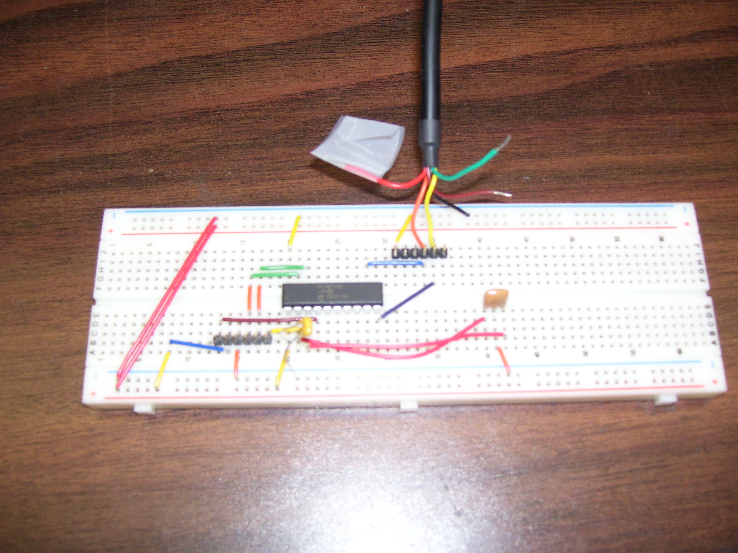
- See breadboard connections for our in-circuit programming
setup on a breadboard. See protoboard for a picture of our
breadboard. A 20 Mhz resonator has been connected to the chip in the picture.
Sample Programs for the PIC Microcontroller
- time2.asm
is an assembly code which reads the timer and sends the data to the PC via
serial. The code has a nice interrupt routine that increments registers
when timer0 overflows. The full clock uses 4 registers.
- timer2.asm
is an assembly code which we use for laser (or photo) gate timing. The program
waits till pin 11 goes low, takes a time stamp, and sends the 4 timer
bytes via serial to a PC. It then waits till pin 11
goes high, takes a time stamp and sends the 4 timer bytes via serial to a PC.
The loop is repeated forever. This program was developed by "CJ" Beccarelli
as part of his senior project.
- atod20hl.asm
is an assembly code which fast analog to digital is done 80 times with the values
stored in memory. The data is then transfered via serial to the PC. The config line
includes the external
20 MHz resonator (_HS_OSC), and serial is transfered at 115.2 KBaud. 10 bit A-to-D
sampling can be done at 300KHz with this program. This program was written by
Michael Mansell as part of his senior project.
Reading the Asynchronous Serial Output from the Chip via the PC Serial Port and USB port
An excellent web site for reading and writting to the serial and parallel
port is "www.beyondlogic.com". Below we list a sample program, which
runs in Linux, to read the serial port.
- picserin.c: This program is written in C
and runs in Linux. It reads the serial port 24 times in succession and
prints the bytes to the screen. We just use it as a test to see if
the PIC chip is transmitting serial data correctly.
- The serial data can also be read via a USB port. The program
usbserial.c: is written in C
and runs in Linux. We use a serial-USB
adapter for which Ubuntu has a driver. Once the USB jack is plugged in,
a device driver "ttyUSB0" is set up.
Timing on the PC via Parallel Port
One can do fairly accurate timing for TTL input using the parallel port.
Below, we list some codes that we use (or have used) in our classroom for
photogate timing.
- pend.c: This program is written in C and runs
in Linux for our pendulum experiment. It checks the parallel port for a
change on pin 10. When a change occurs, a time stamp is obtained using
a call to rdtsc.
- atwoodxpar.c: This program is written in
C and runs in Linux for our atwood machine experiment. It checks the parallel
port for a change on pin 10 on the parallel port. When a change occurs, a
time stamp is obtained using a call to rdtsc. The data can be graphed on
the monitor via the X11 library. To compile use gcc -lm -lX11 atwoodxpar.c
There are translations of this page in Romanian, Ukrainian, Estonian, and Italian.
Links to these translations have been removed.
Siegel's Home Page
Physics Department|
College of Science