The "Mädchen Machen Technik" workshop is designed to give high school students an introduction to microcontrollers. The students will build a flashing light pattern and/or a counter-timer. In the process of building this project, the students will learn about microcontrollers and digital electronics. Here is the parts list for the projects.
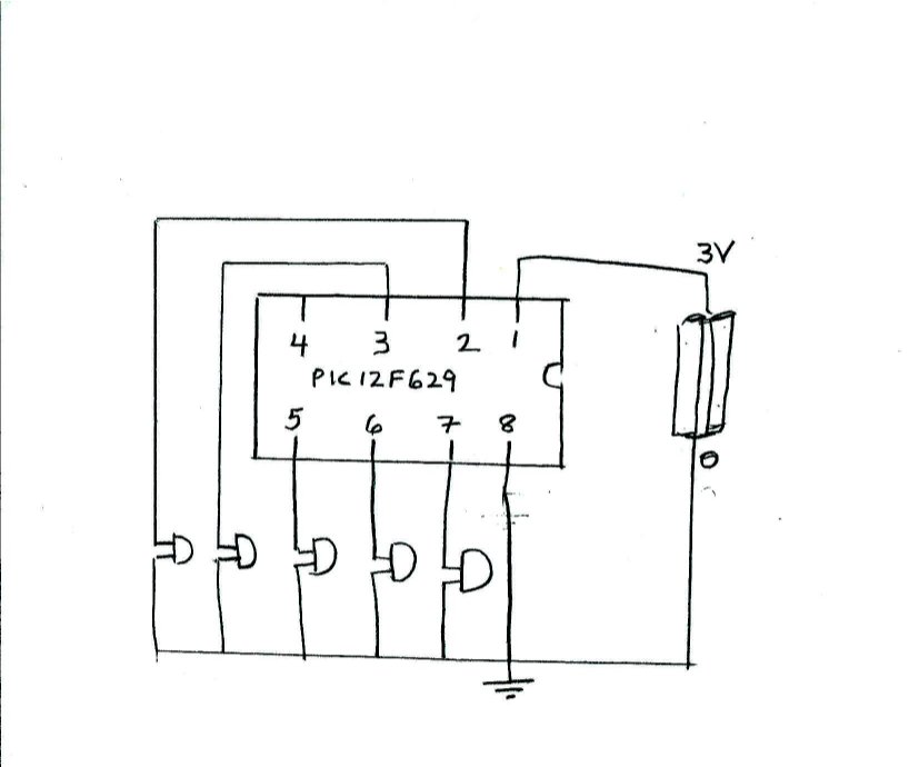
As a first project on the breadboard, we will program the microcontroller to produce a blinking pattern of up to five LED's. We will start with one of the simplest microcontrollers: PIC12F629. First, we build the circuit on the breadboard, then we will program the PIC12F629 chip.
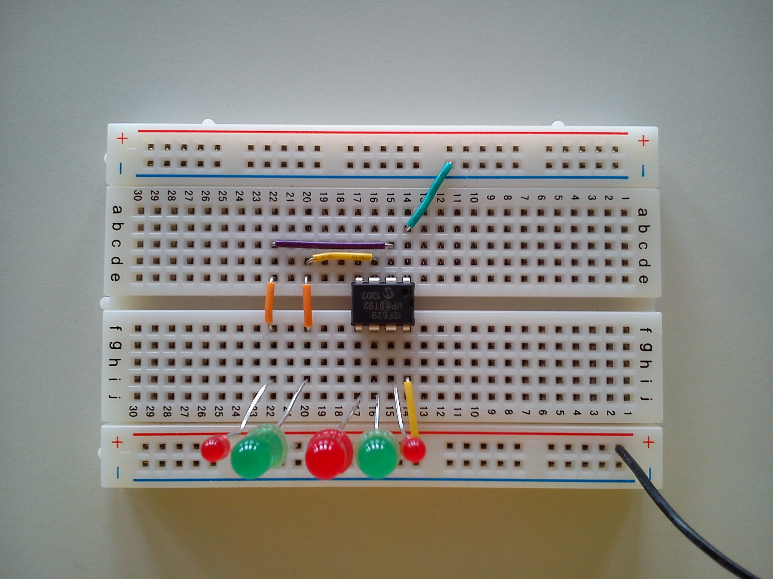
Building the Circuit
After setting up the "blinking lights project" on the breadboard, we program the chip.
To program the microcontroller, we will need to constuct a programmer circuit
on a bread board. Each group of three students will use the same programmer,
a pickit2. The programmer circuit is shown below
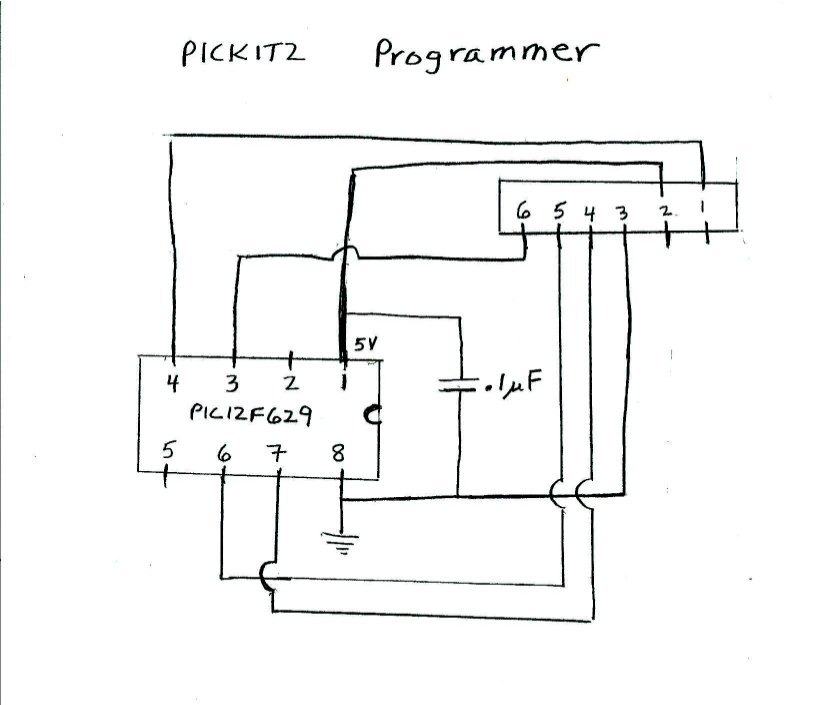
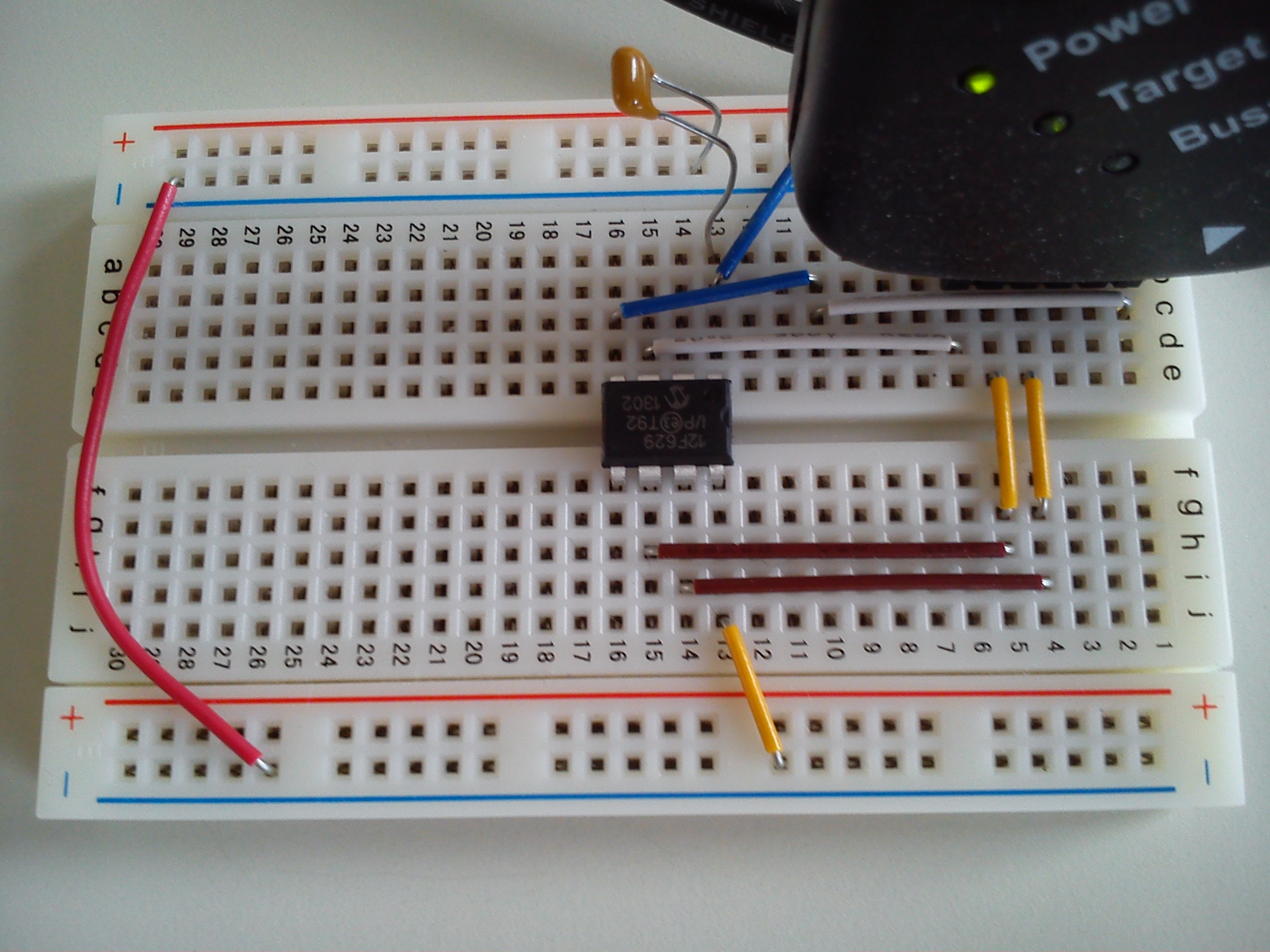
The programmer has 6 pins in a row. The ground on the programmer, pin 3, is connected to the ground of the chip (pin 8). The voltage (5V) of the programmer, pin 2, is connected to pin 1 of the chip. The other programmer pins are connected to the chip as shown in the two figures below:
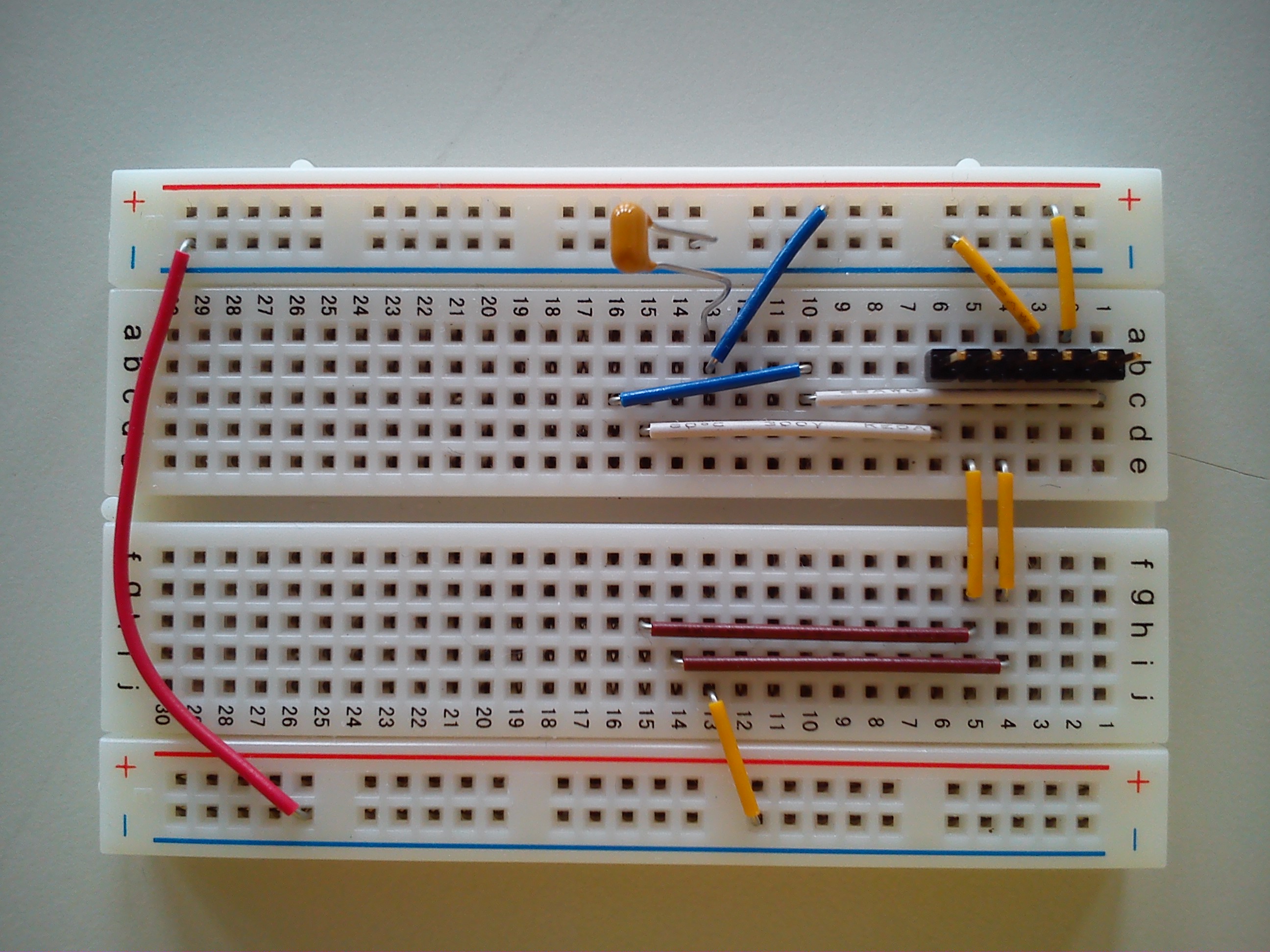
The pickit2 is connected to a personal computer through a usb port. In the picture below, one can see where the microcontroller chip is connected in the programmer:
Finally, we program the microcontroller using the MPlab software from microchip.
Programming the Microcontroller
loop
movlw b'00100101'
movwf GPIO
call delay1
movlw b'00010010'
movwf GPIO
call delay1
goto loop
First, the binary number '00100101' is placed in the working register. Then this number in the working register is transfered into the register GPIO. The GPIO register is directly connected to the pins of the chip. A "1" will put 3 volts on a pin, and a "0" will put zero volts on the pin. The last 6 bits are connected to pins 2, 3, 4, 5, 6, and 7 respecively. The number '00100101' in register GPIO will result in 3 volts for pins 2, 5, and 7, and zero volts for pins 3 and 6. Pin 4 is not affected, it is only an input pin. The subroutine delay1 causes a delay of around 1/4 second.
Then, the binary number '00010010' is placed in the working register and then transfered to the GPIO register. The number '00010010' will produce 3 volts on pins 3 and 6, and zero volts for pins 2, 5, and 7. After a delay of 1/4 second, the chip goes back to "loop" and repeats the pattern.
After experimenting and programming various LED patterns on the 8-pin PIC12F629 microcontroller, the students are ready to work with a larger chip, the PIC16F630. This microcontroller can be programmed with the same programmer circuit that they have already built. The assembly instructions are essentially the same as with the smaller PIC12F629 chip. The PIC16F630 has 14 pins, and can light up to 11 LED's.
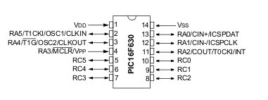
The 14 pins of the PIC16F630 are set up as follows: Pin number 14 (VSS) is ground, and pin number 1 (VDD) is connected to the 3 volt battery. The other 12 pins can be used as digital input/output pins. As before pin number 4 (RA3/MCLR) can only be configured as an input pin. Thus, eleven pins (2, 3, 5, 6, 7, 8, 9, 10, 11, 12, and 13) can be used as digital output pins. These eleven pins can be connected to LEDs. There are two memory addresses that control the 12 free pins: one called PORTC and another called PORTA.
The PORTC memory address bits are labeled: (RC7,RC6,RC5,RC4,RC3,RC2,RC1,RC0), and the PORTA memory address bits are labeled: (RA7,RA6,RA5,RA4,RA3,RA2,RA1,RA0). From the figure below, one can see which bits in PORTC and PORTA are connected to the pins on the chip.
The first two bits are not connected to any pins, and the next 6 bits are connected to pins 5 through 10. If the binary number b'00101010' is placed in PORTC, then 3 volts will be set on pins 5, 7, and 9.
For PORTA, the bits connect to the following pins:
As with the smaller chip, pin4 can only be used as an input pin. The binary number b'00110010' will result in 3 volts set on pins 2, 3, and 12.
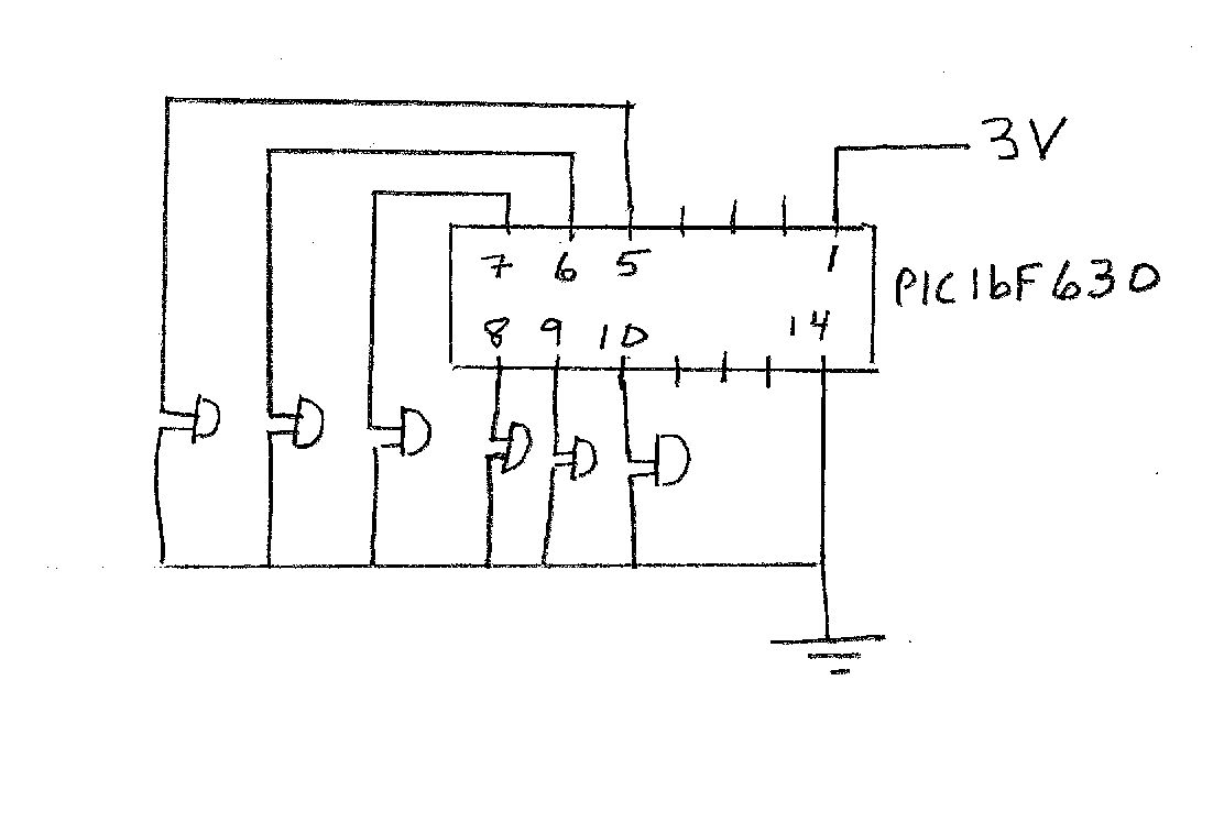
The students will start by turning on and off the 6 output pins that are controlled by the PORTC address. They will set-up 6 LEDs in a row that connect to the pins 5, 6, 7, 8, 9, and 10 as shown in the diagram below:
Once the LEDs are setup on the breadboard, the assembly code led11.asm can be programmed into the PIC16F630, using the same programmer circuit as for the smaller chip. The important lines of the code are
loop
incf PORTC
call delay1
goto loop
The command "incf" increments PORTC by one. That is, the value in PORTC is increased by one. The students will now run the program and notice how the LEDs light up. We will now discuss the binary number system.
There are a number of "Take Home Projects" the students can do. They can use either the small chip (PIC12F629) and program in any light pattern of your choice for up to 5 LEDs. Or, they can use the larger chip (PIC16F630) and program in any light pattern for up to 11 LEDs. The light patterns can be decorative. The students can also make a counter, or a timer. The timer project is described below. The students should first set up their "Take Home Project" on the breadboard, and program the chip. Once they are certain that it will work, then (if there is enough time) they can build another one on a circuit board where the wires can be soldered together.
The timer project is a timer that can be set up to 63 minutes. A button is used to set the minutes. Once the time has elapsed, the LEDs flash. Below is a picture of the timer set up on a breadboard:
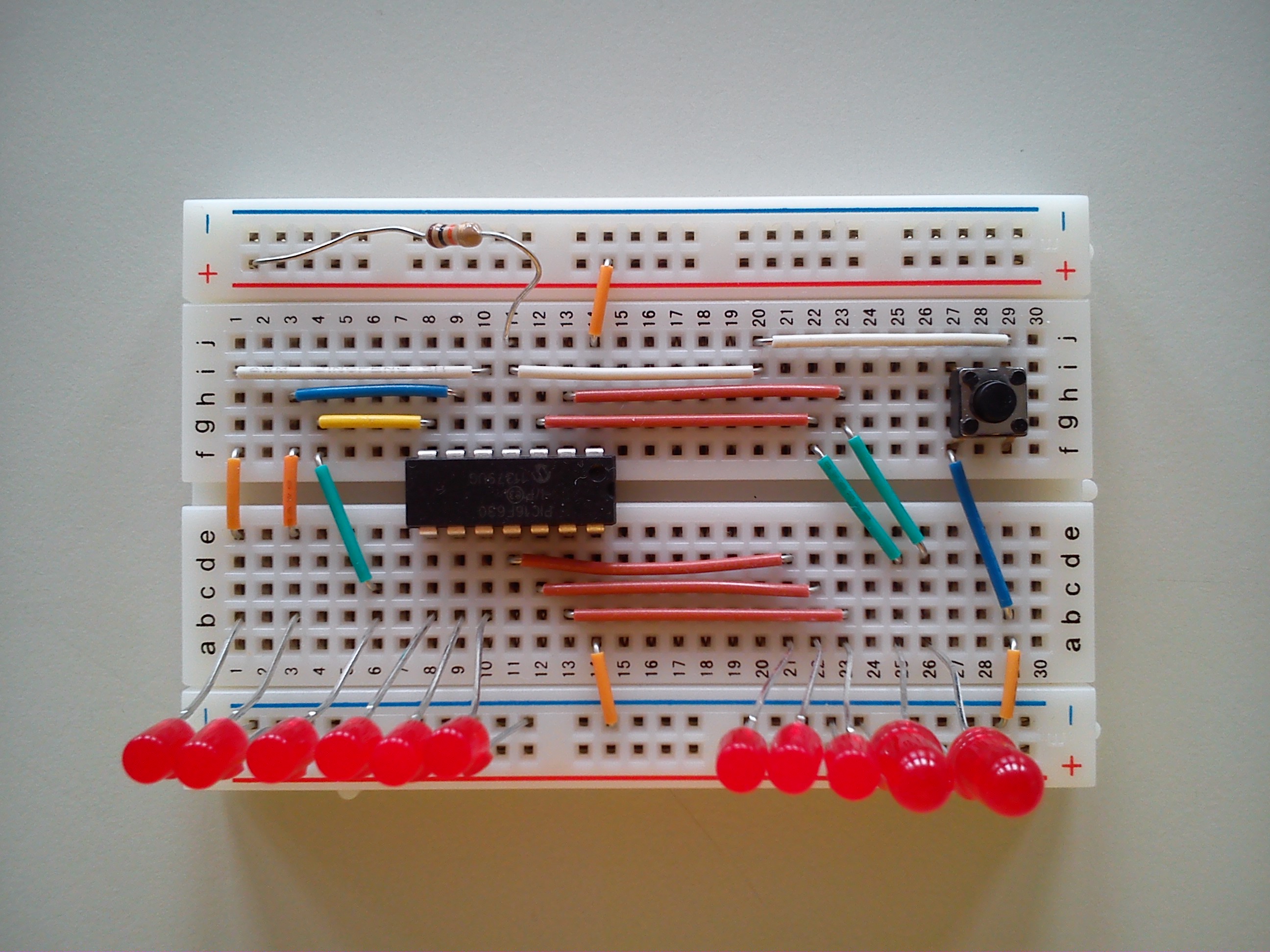
The assembly code for the timer is timer1.asm.