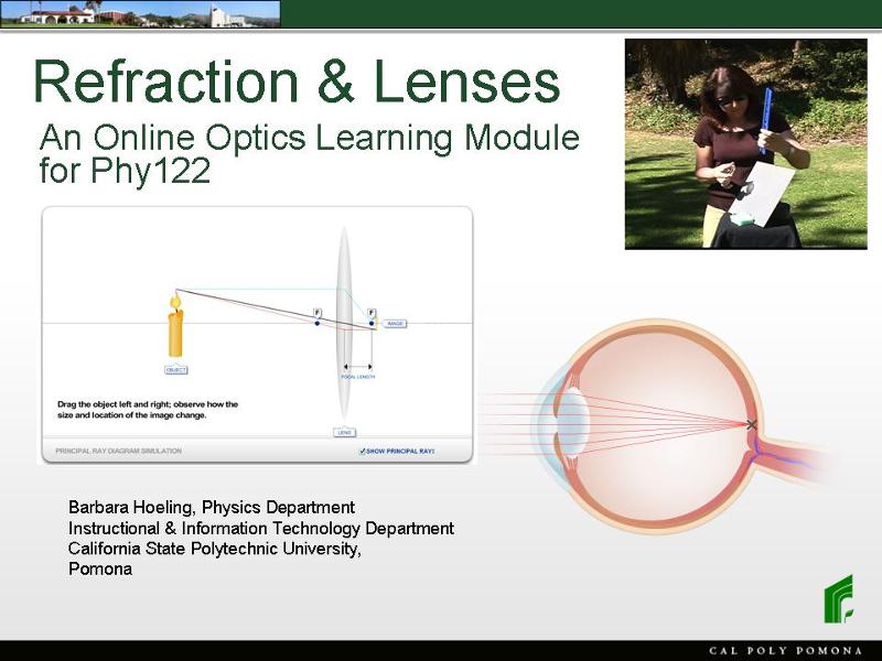
Refraction & Lenses
an Online Optics Learning Module for Phy122
In this online learning tool, you can study how light rays refract, what Snell's law is and how to use it, how a convex lens produces a real or a virtual image, and how a concave lens produces a virtual image. You can also see applications of these principles demonstrated in the problems that are solved in the videos.
Let me explain briefly how you should work with this tutorial. The tutorial contains pages with graphics and narration explaining the physics. There are also interactive animations that allow you to do "virtual" experiments, and to explore these concepts in more detail. Please take your time playing with the interactive animations, and make sure you are observing carefully what happens.The questions posed throughout the tutorial are meant to guide you in your studies, and to help you identify the key points you have to understand.
One more remark: In this tutorial, you are using the ray model of light, which describes light rays as propagating in straight lines. This is in contrast to the wave model of light, which describes light as an electromagnetic wave. Certain optical phenomena, such as interference and diffraction, can only be understood within the framework of the wave model of light, and will therefore not be considered in this tutorial.
Have you ever observed what happens when you stick a pencil in a glass of water, and then look at it from different directions? This picture shows you that the pencil doesn't seem to be straight any more, it looks like it has a kink! What does this mean?
Shining a laser beam, for instance from a laser pointer, onto a bowl of water can give us a clue: the light beam does not continue straight at the border between air and water, it has a kink! The phenomenon is called refraction: a light ray bends when it goes from air into water, or vice versa, or from glass into air, or vice versa – generally, when it goes from one medium into another. When we use optical lenses, we are taking advantage of the refraction of light.
This cartoon shows you a marching band, walking from an area of solid ground where the musicians can walk fast, into a region of muddy ground where they have to walk more slowly. Each row of musicians carries a long pole. Watch what happens when the first person of a row enters the muddy ground: the direction of the pole changes lightly. As more marchers of the same row come to the muddy ground, the pole rotates further. The only reason for this change in direction is the fact that the people walk at different speeds on the solid and muddy grounds. Interesting, isn't it? You can try this out yourself with same friends by marching in a row, holding a meter stick. This analogy can explain how the kink in the light ray comes about when the light enters a medium of different index of refraction, i.e., a region where its speed of propagation is less. The pole along the row of marchers symbolized the wave front, and the light beam propagates perpendicular to this wave front. As the wave front changes direction because of the different speeds of light in the different media, so does the light beam. And that's how light beams get kinks when you shine then at an angle from one medium into another: simply because light propagates with different speeds in different media. The speed of light in a medium is given by c/n, where n is the index of refraction of the medium. So you can see that the higher the index of refraction of a medium, the slower light moves in that medium.
This interactive animation allows you to explore Snell's law by shining a laser from air into a different medium, which can be either water or glass. Move the laser to change the angle of incidence, and observe how the refracted beam changes direction accordingly. The angle of incidence and the angle of refraction are marked theta i and theta r, respectively. Note that these angles are always measured relative to the normal, i.e. to the line perpendicular to the refracting surface. Make sure you observe carefully in which direction the beam is refracted when it propagates from the medium with the smaller index of refraction to the optically denser medium, i.e., the one with the larger n.
In this problem, we are applying Snell's law.
This animation is very similar to the previous one. It allows you to explore Snell's law again, only now you can shine the laser beam from any direction you like. You are free to select the media for the upper and lower part of space from the drop-down lists. Now you should observe the following: shine the laser from the optically denser medium (which you can recognize by the darker blue color) into the lower n medium. Start at normal incidence, with the laser hitting the surface perpendicular, and move it to larger angles of incidence. Since the light is going from a higher n medium to a lower n medium, the beam is refracted *away* from the normal. Now you can observe that something strange happens when the refracted beam is at a right angle to the normal, i.e. going parallel to the interface between the two media. If you increase the angle further, there is no more refracted beam in the other medium, the beam is instead *reflected* from the interface, like from a mirror. This is called "total internal reflection". It is the basic principle that allows light to propagate in an optical glass fiber. Keep playing with the animation until you feel that you understand how total internal reflection works. Think about the following questions: What are the conditions for the two media for total internal reflection to occur? How could you calculate the smallest angle of incidence for which total internal reflection happens, as a function of the two indices of refraction n1 and n2? This angle is called the critical angle, and it is important for example for fiberoptics.
We just observed how a convex lens bundles the light rays from the sun into a single bright spot. This means that a convex lens refracts light in a very special way, as this graphic will illustrate. It shows a lens from the side, and light rays coming in from the left. Rays near the middle of the lens are not changing direction very much. But rays that hit the lens closer to its rim are bent much more, such that all rays meet in one point, the focal point of the lens. The distance between the lens and the focal point is called the focal length of the lens. As we have shown in our experiment in the sun, a thicker lens has a shorter focal length than a thinner lens.
Footnote: To understand in more depth why light rays that hit the lens closer to its rim are bent more than rays hitting in the middle, consider the angle of incidence near the rim, vs. in the middle. You might want to go back to Snell's Law on page 4 to remind yourself how the angle of incidence is measured: relative to the normal of the glass surface. So, closer to the rim, the angle of incidence is greater than in the middle of the lens. The same goes for the angle of refraction. And that's why light rays are bent more when hitting the lens near its rim!
We have seen in the last video that a convex lens indeed makes an image of our object, the little lit arrow. But how exactly is this image formed? This animation shows you that light rays are going off in all directions from every point of the object. Let's look at one specific point of the object, say the very tip of the arrow. We know that the lens makes all light rays that are coming from this one point converge in one other point, the image of the tip of the arrow. But how do we know where this image point is located? There are three special rays for which we actually know the path. These three rays are called the principal rays. The first one is the one that hits the lens in the middle and goes right through without changing direction. The second one is the ray that goes parallel to the optical axis, so it hits the lens right on, the same way the sun rays hit it in the first experiment. Of course we know where such a ray goes: through the focal point! Now we can see where the image point of the tip of the arrow is located: at the intersection of these two principal rays! We can draw in a third principal ray just for confirmation: A ray that goes through the focal point of the lens leaves the lens parallel to the optical axis. And indeed, this ray also crosses with the two others in the same point! We can now find the image point for every point of the object in the same way - we can construct our image. What we find for the configuration that is shown here is: The image is smaller than the object, the original arrow, and it is upside-down, just as we observed in the video. So for this particular distance between the object and our lens, we are getting a reduced, inverted image.
Here you can see what is called a principal ray diagram. We have constructed the image of the candle from the three principal rays, as we explained before. This interactive animation allows you now to move the object relative to the lens, and to observe what happens to the image. Click on the object, the candle on the left, and drag it to different positions. The three principal rays are always constructed the same way: one goes straight through the middle of the lens, one goes parallel to the optical axis, and then through the focal point, and one goes through the focal point between the object and the lens, and leaves the lens parallel to the optical axis. Take some time moving the object back and forth, and try to answer the following questions: What happens to the position of the image when you move the object closer to the lens? What happens to the size of the image when you move the object closer to the lens? You will notice that the animation does not allow you to move the object closer than about two focal lengths to the lens. That's because we are trying to simulate the situation for our eye: Everything we look at is a lot further away from our eye than the size of our eyeball, which is about one inch in diameter. We'll come back to this in a moment. For now, make sure that you also observe what happens when you move the object further and further away from the lens. Where does the image move? Remember what we concluded from our experiment in the video about the position of the image of a very far away object? Is this consistent with the result of this simulation?
On this slide, you see a schematic of a principal ray diagram. By identifying two sets of similar triangles, we will be able to derive the thin lens equation. Let's first define the variables: i is the image distance, and o the object distance; f is the focal length; hi is the height of the image and ho the height of the object.
The triangles ABC and ADE are similar, so the ratio of their horizontal sides, i divided by f, is equal to the ratio of their vertical sides, hi +ho divided by ho. This is equation (1). The triangles KGC and DHC are also similar, so hi divided by ho is equal to i divided by o. This is equation (2). This one is easy to remember: hi over ho equals i over o!
Take a moment to study the geometry! Use equations (1) and (2) to derive the thin lens equation 1/f = 1/i + 1/o by yourself. On the next slide, you'll see the algebra performed, so you can compare it to your work.
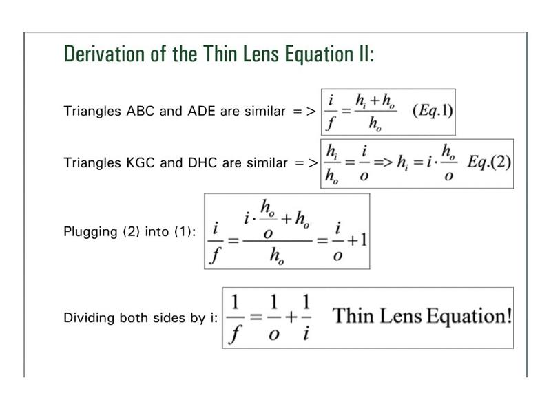
Here we derive the thin lens equation, starting from the two equations of the previous slide that we obtained by considering two sets of similar triangles: eq.(1): i/f = (hi + ho)/ ho , and eq. (2): hi /ho = i/o. We can solve eq.(2) for hi : hi = i*ho /o. Now we plug this expression for hi into eq. (1), and we obtain: i/f = 1/ ho *(i* ho /o + ho). Cancelling ho yields: i/f = i/o + 1. Finally, dividing both sides by i gives the thin lens equation: 1/f = 1/o + 1/i .
A camera is basically a little box with a convex lens in one side and a screen, the polaroid film, on the opposite side. In this problem, we are applying the thin lens equation to figure out where we have to move the lens relative to the film, to get a focused image of an object a certain distance away.
Let's now construct the principal ray diagram for a concave, i.e., a diverging lens. The idea is the same as for the convex lens: we will consider how the three particular rays for which we know what happens are refracted by the concave lens: The ray going through the center of the lens will continue straight. The second ray, the one parallel to the optical axis, will get refracted as if it were coming from the focal point of the lens. Remember that the concave lens spreads out parallel light rays as if they were originating from the focal point. The third ray is the one that leaves the lens parallel to the optical axis, so it's the reverse of the second. It's a little trickier to construct: draw in the line from the object through the focal point on the other sight of the lens, and then the parallel to the optical axis from the point where this line intersects the lens. As expected, all three rays intersect in one point, the tip of the image of the arrow. This image is located on the same side of the lens as the object, and it is upright and reduced in size compared to the object. It is called a virtual image, meaning that you could not see it on a screen if you were going to put one at its position. However, you can see it (just like the image in a mirror) when you look at the lens from the right, because the light rays emerge from the lens *as if* they were coming from the reduced, upright, virtual image. This is true no matter where the object is located relative to the focal point. A concave lens always forms a virtual image that is upright and smaller than the object.
Here you have another principal ray diagram, just like the one we constructed on the previous page, only this one is interactive. You can click on the object and drag it, and observe what happens to the image. Notice that, as we saw on the previous page, this image is a virtual image. To remind you of this, it is shown striped. "Virtual image" means that the light rays are not actually coming from the position where the virtual image is located – nothing is really there. But the light rays emerge from the lens *as if* they were coming from the virtual image. Move the object back and forth to see what happens to the image. As you can see, a concave lens always produces an upright, reduce, virtual image.
This interactive animation is very similar to the one with the convex lens you have used before. Here, too, you can click on the object and drag it to different positions, so you can observe what happens to the image. But now, you are able to move the object not only up to the focal point, but even closer to the lens. Look what happens when the object passes the focal point! Suddenly, the real image is gone, and a virtual, enlarged image appears instead as soon as the object gets closer to the lens than the focal point. Again, since this is a virtual image, it is shown striped. Play with this animation until you feel you understand what happens. Make sure you are able to answer the questions: For what object distances does a convex lens produce a real image? For what object distances a virtual image?
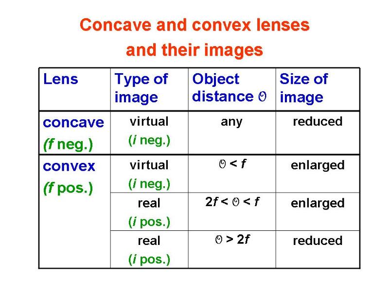
This table summarizes our results for the images of a concave and of a convex lens. The case of the concave lens is simple: it always produces an upright, reduced, virtual image. For the convex lens, things are more complicated. If the object is further away from the lens than the focal point, the convex lens makes a real, inverted image. However, if you move the object closer than the focal point, the convex lens produces a virtual image that is upright and larger than the object.
Two Lenses in Combination: