|
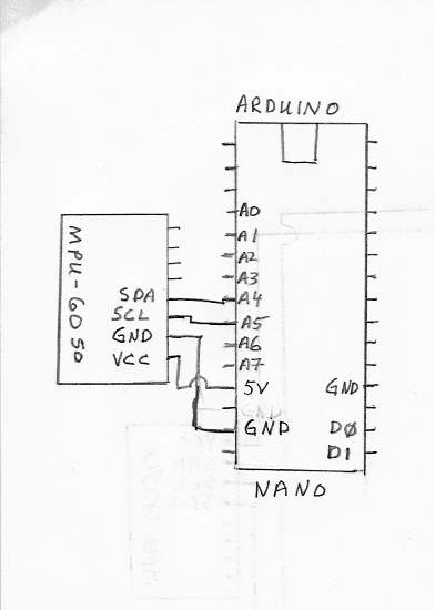
In this project we use the Arduino Nano and the MPU-6050 accelerometer. The Arduino Nano receives the data from the accelerometer via the I2C SDA and SCL pins. The wire connections are very simple as shown in the figure on the right: |
|
Below I list some projects for the Arduino microcontrollers that can be used in a Physics or Engineering laboratory as well as projects for the hobbiest.
|
In this project we use the Arduino Nano and the MPU-6050 accelerometer. The Arduino Nano receives the data from the accelerometer via the I2C SDA and SCL pins. The wire connections are very simple as shown in the figure on the right: |
|
After reading the byte values, the code calculates the x-, y-, and z- components of the acceleration in units of cm/s2.
|
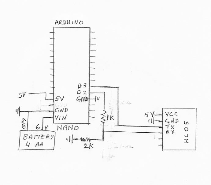
In this project we check the bluetooth function of the Arduino Nano. The bluetooth module HC-05, or HC-06 is connected to the Nano as shown in the figure on the right. We use pin D2 to transmit the data from the Nano, which is connected to the RX pin of the HC-05. Pin D3 would receive data from the HC-05 and is connected to the TX pin of the HC-05. The 1K and 2K Ohm resisters serve as a voltage divider, since the RX pin of the HC-05 can only handle 3.3 Volts. The voltage on the digital pins on the Nano are 0 or 5 volts. The battery connected to VIN consists of four AA batteries yielding 6 volts. A voltage converter in the Nano reduces this value to 5 volts for the Nano's operating voltage. |
|
|
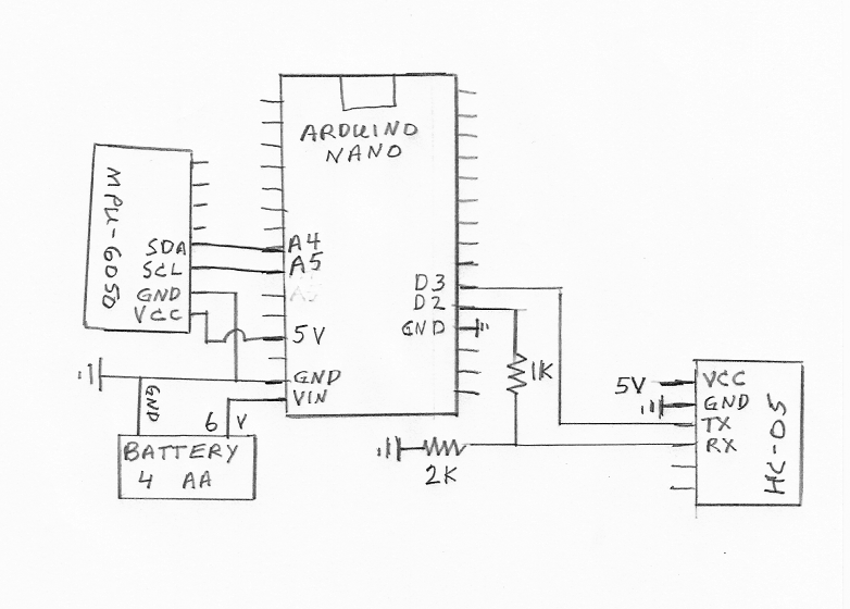
In this project we use the Arduino Nano with the MPU-6050 accelerometer and the HC-06 (or HC-05) bluetooth module to measure acceleration and transfer the data via bluetooth. The Arduino Nano receives the data from the accelerometer via the I2C SDA and SCL pins. The bluetooth module HC-05, or HC-06 is connected to the Nano as shown in the figure on the right. We use pin D2 to transmit the data from the Nano, which is connected to the RX pin of the HC-05. Pin D3 would receive data from the HC-05 and is connected to the TX pin of the HC-05. The 1K and 2K Ohm resisters serve as a voltage divider, since the RX pin of the HC-05 can only handle 3.3 Volts. The voltage on the digital pins on the Nano are 0 or 5 volts. The battery connected to VIN consists of four AA batteries yielding 6 volts. A voltage converter in the Nano reduces this value to 5 volts for the Nano's operating voltage. |
|
To program the Arduino and read the output, we use a Raspberry Pi.
The Arduino Nano is programmed with the code:
BTaccel.ino
using the Arduino IDE software. The six byte values for ax, ay
and az are sent to the bluetooth module via serial bluetooth. The bytes
are received and read by the Raspberry Pi from the dev file /dev/rfcomm0 using the C code:
BTaccelread.c.
After reading the byte values, the code calculates the x-, y-, and z- components of the acceleration in units of cm/s2.
The overflow interrupt therefore produces two unsigned int variables tim1 and tim2. These two variables along with TCNT1 yield a 48 bit counter that increases at the rate set by the prescaler. in Timertest.ino we have set the prescaler to 1, TCCR1B |= (1 << CS10);. With the prescaler set at 1, TCNT1 increases at a rate of 16X106 times per second. The three 16 bit numbers (tim2, tim1, and TCNT1) are each separated into their bytes (t0, t1, t2, t3, t4, and t5) and sent via serial to be re-combined for an accurate time stamp. One can reduce the timing rate by changing the prescaler. If the prescaler is changed, then one might need fewer bytes for the timing.
|
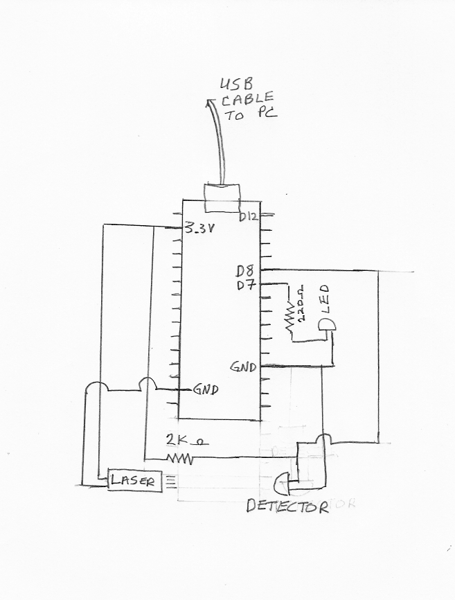
In this project we use the Arduino Nano with a laser and a photodiode. The Nano detects when the photodiode is blocked and unblocked from the laser light. The nano then sends the time data via the usb connector to a computer. The blocking time data is read from the device file ttyUSB0 via a C program or one written in nodeJS. When the laser light is incident on the photodetector, the detector's resistance is low, around 600 Ohms. When the light is blocked, the resistance of the photodetector is high, around 4000 Ohms. A pull-up resistor of 2000 Ohms is in series with the detector, so that when the light is incident on the detector pin 8 reads LOW. When the laser light is blocked, pin 8 reads HIGH. A red led is connected to pin 7 to show if the detector is unblocked or blocked. The pin diagram is shown in the figure to the right. |
|

To program the Arduino and read the output, we use a Raspberry Pi.
The Arduino Nano is programmed with the code:
Lasergate.ino
using the Arduino IDE software.
We use two different programs to record and analyze the data. Two in C: tandvfly_arduino.c and conaccfly_arduino.c, and the corresponding two in nodejs: tandv_arduino.js and conacc_arduino.js. For the program starting with tandv, one inputs the number of blocks and the effective thickness of the blocking tabs. The program starting with conacc can be used if one knows that the motion of one of constant acceleration. Links to the four codes are:
Each of the above programs reads the data from the arduino nano via the device file ttyUSB0, found in the linux dev directory. The C programs can be programmed in linux using gcc. We have also made a boot image, which uses Puppy Linux, and can be used in a 64 bit Windows or Linux operating system. Just "burn" the image file lasergate64_arduino.iso to a CD or usb flash drive. Then, set the boot order to start with the lasergate64_arduino.iso. To run the tandv or conacc programs, just right-click on the icon and "run in terminal". We use the boot-CD in our laboratory classes.
For the air friction experiment in the sensorics lab, the program pend_exp_40.c is used to collect the data and make a text file, astardata.txt, which lists the speed and astar. The html program astarfit.html is used to analyse the file astardata.txt, which contains the a* data.
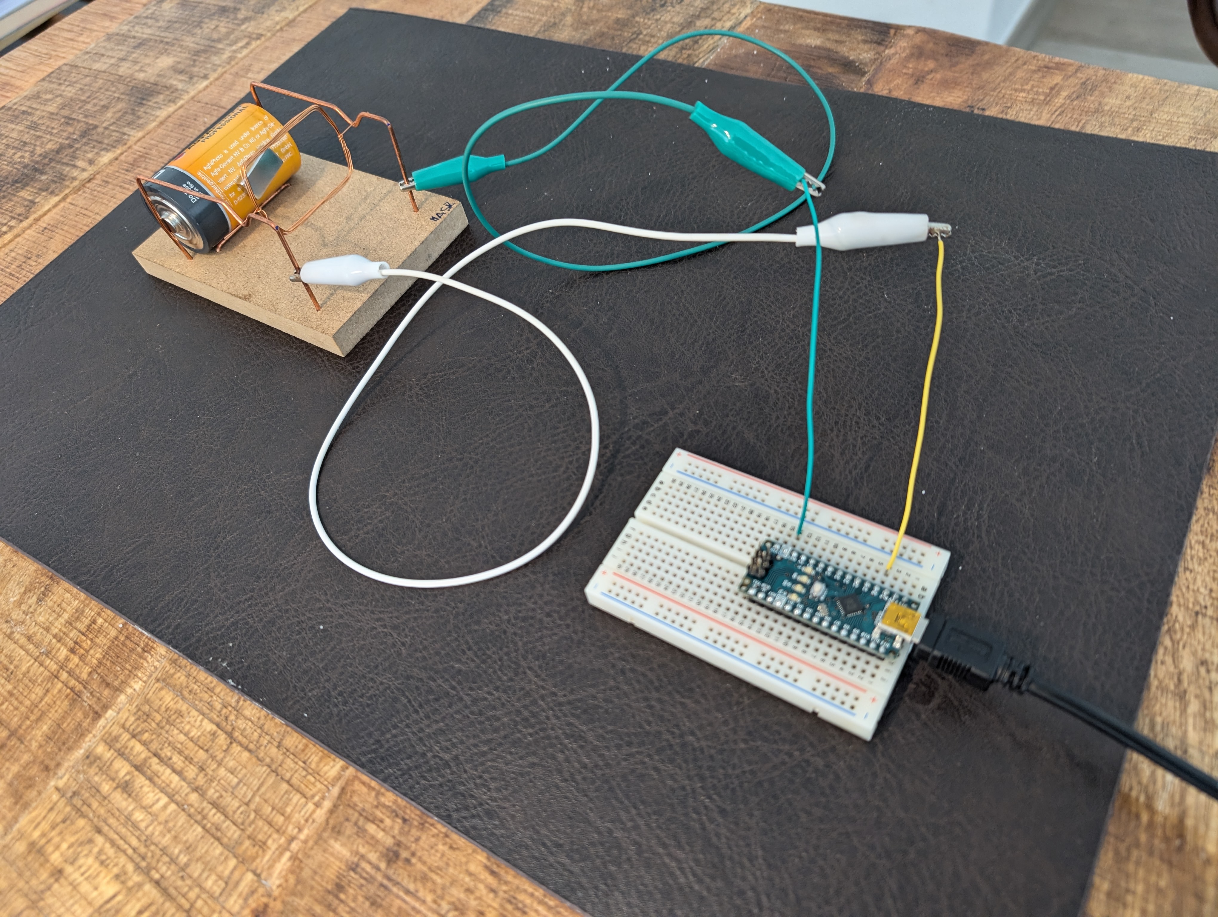
In this project we use the Arduino nano to measure how fast the "Johnson" electric motor is spinning. The Johnson motor is a simple electric motor that we use for different student groups of ages 10-17 years that visit our university. The motor consists of two support wires, a D cell battery, a very strong magnetic and a rotating (armature) wire. The rotating armature gets a "kick" from the magnet when current flows through it. The motor, shown in the picture below, is built by the students. The students form the two support wires and wind the armature (rotating wire). On the shafts of the armature, the students sand off the plastic coating such that the armature gets a "kick" once a cycle when it conducts current.
In order to check if the correct voltages are being read and to troubleshoot any problems in measuring the times, one can use the arduino code readvoltage.ino. This program simply measures A0 and sends the data via serial ttyusb0 to the computer. The c program voltread.c can be used to read and display the voltages.